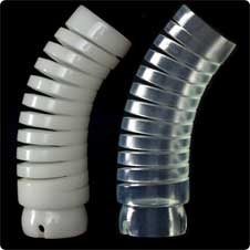

The industry standard for rapid prototyping is the .STL file, a file extension that stands for StereoLithography. Basically, it's a file that uses a mesh of triangles to form the shell of your solid object, where each triangle shares common sides and vertices. Most CAD packages will allow you to export to the .stl file format, and providing TECH, INC. with good .stl files will assure you a speedy quote turnaround, and good quality SLA models. Here are some things you should know about .stl files.
Faceting: The relative coarseness or smoothness of a curved area is called a feature's faceting. Faceting is controlled by the output settings of the CAD package being used, the most common variables are deviation or chord height, and angle control or angle tolerance. Before we get into the specifics of each, let's first focus on the desired outcome�
 |
 |
 |
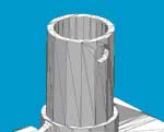
Coarse Faceting |
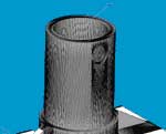
Excessively Fine Faceting |
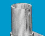
Good Quality Faceting |
Coarse Faceting : In the image to the left above, you can see how coarse the faceting is. Instead of a nice round boss, the curve almost resembles a stop sign. What will happen with this file is the feature will build a little small on the outer diameter, and a little small on the inner diameter, because the laser will cure the resin in the planes that are defined by the straight lines. Coarse faceting is caused by the Angle settings being too high, or the deviation/chord height settings being too large, or a combination of both.
Excessively Fine Faceting: The image in the center is an example of excessively fine faceting. Though the inner and outer diameters are very circular and to the file dimension, the file size itself is at least 5x larger than it needs to be, which causes excessive prep time and setup time, and inaccurate quoting. Also, the degree of detail in the file far surpasses any rapid prototyping process, including Stereolithography. Most lasers are about .010�-.015� in diameter, so asking a laser to define a feature to .0001� detail is analogous to performing drafting with a felt tip marker. This condition is caused by the Angle settings being too low, or the deviation/chord height settings being too small, or a combination of both.
Good Quality Faceting : The happy medium between the two extremes is good quality faceting, just detailed enough so that features build to the file dimensions, while being simple enough to maintain a manageable file size, without a superfluous amount of detail. In most cases, this can be obtained using .001� or .002� for deviation or chord height, and a modest angle setting. These settings will vary depending on your specific part, and your CAD package, so it's always a good idea to double-check your .stl files before sending them to TECH, INC. Also, the file size of a good .stl file is usually 5MB or smaller.
STL File Verification
So how do I know if my .stl files are good ones? If your CAD package has the option, select 'Show STL Info Before File Saving' or 'Preview' when making your .stl files. By using this method, you can see the type of output quality before saving the file.
Making .stl files from SolidWorks
Click on file, save as. Select the path where you wish to save the file.
For File Type, use the drop-down arrow, choose .stl. Click Options.
Options - select Binary for file type. Binary files are approximately 1/5 the size of ASCII files.
Options - Total Quality: Choices are Coarse, Fine, and Custom. Choosing Custom allows access to Total Quality and Detail Quality sliders and fields. In most cases, selecting Fine will produce an acceptable file, for custom try entering .001'' or .002'' for Deviation, and 10 degrees for Angle Tolerance.
Check the 'Show STL Info Before File Saving' or 'Preview' box to see a faceted view of the .stl file you are creating.
Select 'Done', and send the file to TECH, INC.
Making .stl files from ProEngineer
Click on file, save as.
Select the file type STL.
In the Export STL dialog box, set Format to Binary. Binary files are about 1/5 the size of ASCII files.
Set the Chord Height to .001�. The field will be replaced by a minimum acceptable value for the geometry of the model.
Set Angle Control to .5.
Name the file and click the OK button. Pro/Engineer will save your STL file, and display your triangles on the screen.
1. Select File, Export, then Rapid Prototyping
2. Make sure it's binary, set triangle to .001'' or .025mm.
3. Type in the file name, make sure the extension is .stl, then select OK.
4. In class selection, select all, then ok.
5. Then discontinue, then ok.